Transfer of forces through the structure
We introduce some demands for the statical way of behavior of the components.
Slab function - the ability to transfer loads perpendicular to the plan of the component.
|
Wall function – the ability to transfer loads parallel with or just inside the plan of the element.
 |
Column function – the ability to transfer loads parallel with the longitudinal axis.
 |
Beam function – the ability to transfer loads perpendicular to the longitudinal axis.
|
|
The methods of the analysis
|
|
|
|
|
|
|
|
|
|
|
If the wall has 1 fixed support line it is moveable. |
|
|
|
If the wall has 2 fixed support lines it is moveable. |
|
|
|
If the wall has 3 fixed support lines it is stable. |
In the determination of how to transfer the forces we introduce some demands for statical way of behavior of the structure.
Early in the outline proposal phase you determine the transfer of forces in the overall statical system of the structure
At this time you are normally not bounded by certain choice of materials and therefore the determination of the transfer of forces can be determined entirely by statical principles .
Furthermore you combine the building components to form a structure which is global stable.
Principles
Principles to reach these goals can be one or more of following:
a) To set up statical demands of behavior of the individual building components.
b) To use "self bracing" building components in the structure
c) To use bracing triangles (additional constructions).
d) To identify the transfer of forces from one building component to another.
ad. a)
There are worked with demands for functions to the individual building components.
Slab function
The ability to resist loads perpendicular to the planar face.

Wall function
The ability to resist loads in plan with the component.
|
|
|
Beam function
The ability to continue loads perpendicular to the longitudinal axis.

Column function
The ability to continue loads inside the planar of the element.
ad. b)
Of common existing system can be mentioned:
|
Column-girder system with cantilevered columns. |
|
|
2-charnier arch. |
|
|
2-charnier frame with moment stiff corners. |
|
|
3-charnier frames with moment stiff corners. |
|
ad. c)
Triangle constructions
|
Diagonals made as tension and/or compression bars. In the structure they act as stable simple triangles or truss. |
|
ad. d)
|
This could be essential for the design of the joints.
For instance: · How are horizontal forces transferred from a diaphragm to the end of house. · How is a force transferred from a wind bracing to the structure below. |
|
The individual building components
There is of course also demands to the stability of the individual building components where the component becomes unstable for at specific load called the stability load.
The components will additional be loaded for instance by forces caused by temperature fluctuation, eccentric acting forces due to deviation in execution ect.
Attention to those forces must be taken later in the engineering design phase.
Below follow examples showing how the transfer of forces can be identified and how to illustrate it during the planning.
This can be performed in many different ways. Here two essentially different methods are shown.
Method A: A mixture of text and sketches.
Method B: A strictly schematic form.
Example 1
|
Determination of the transfer of forces in a minor single-story building. Outline - example Extract of construction description Roof construction: Masonry: Light weight facades: |
|
Method A
Disposion
of the transfer of forces.
| Wind load on facades The load is transferred by the wall to the wall foundation and the roof. The wall has a slab function. Through the stiffness of the roof area (shear function or wind bracing) the load is leaded to the gable areas, that by shear function deliever the load to the foundation of the gables. |
 |
|
| Wind load on gables The load is transferred by the wall area to the facades by slab function, and then by wall function to the foundation of the facades. |
 |
|
| Vertical load The load from the roof area is transferred through the trusses (beam function) to the facades and then through beams, columns and masonry to the foundations (column function). |
 |
|
Method B
|
Disposion to force transferring Signature: BF = beam function SF = slab function CF = column function WF = wall function WB = wind bracing
|
|
|
Wind load on facades
|
|
|
Wind load on gables
|
|
|
Vertical load
|
|
Example 2
|
Determination of the transfer of forces in a minor single-story hall building. Outline - example Extract of construction description
Load bearing structure: Roof construction: Masonry: |
|
Method A
Disposion to course of forces.
|
Wind load on facades The load is transferred from the wall area by slab function to the 3-charnier arches and by their self stiffening function they transfer the load further to the pad foundation in the facade. |
 |
|
|
Wind load on gables The load is transferred from the wall area by beam function to vertical wind beams and then further to gable foundation and roof area. Through the purlins of the roof area (compression members) the load is transferred further to wind bracings and then by tension to the foundation of the facade. |
 |
|
|
Vertical load The load from the roof area is transferred through the purlins (beam function) to the 3-charnier archs in the structure. By beam-column function the arches transfer the load to the pad foundations in the facade. |
 |
|
Method B
|
Disposion to force transferring Signature: BF = beam function SF = slab function CF = column function WF = wall function WB = wind bracing
|
|
|
Wind load on facades
|
|
|
Wind load on gables
|
|
|
Vertical load
|
|
Example 3
|
Determination of the transfer of forces in a minor two-story building. Outline - example Extract of construction description Roof construction:
Ceiling construction:
Suspended floor: Walls: Second
floor: |
|
Method A
Determination of the transfer of forces.
|
Wind load on facades
Second floor: The load is transferred from the wall area by beam function to suspended floor and roof area.
Through the wind bracing of the roof area the load is transferred to the gable areas that by wall function transfer the load to the foundations of the gables.
First floor: The load is transferred from the wall area by slab function to the foundation of the facade and the suspended floor.
Through the wall function of the suspended floor the load is transferred to the gable areas that by shear function deliver the load to the foundations of the gables. |
 |
|
|
Wind load on gables
Second floor: The load is transferred from the wall area by beam function to suspended floor and roof area.
Through the wind bracing of the roof area the load is transferred to the facades that by wall function transfer the load to the foundations of the facades.
First floor: The load is transferred from the wall area by wall function to the foundation of the gable and the suspended floor.
Through the wall function of the suspended floor the load is transferred to longitudinal wall and facades that by wall function transfer the load to the foundations. |
 |
|
|
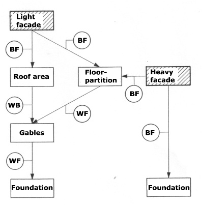
Vertical load
The load from the roof area is transferred by the trusses by beam function to the light weight facade that by beam- and column function transfer the load further
The load on the suspended floor is transferred by slab function to the facades and the longitudinal wall and from here further down to the foundation by column function. |
 |
|
Method B
|
Disposion to force transferring Signature: BF = beam function SF = slab function CF = column function WF = wall function WB = wind bracing
|
|
|
Wind load on facades
|
|
|
Wind load on gables
|
|
|
Vertical load
|
|